Why vgs is negative in jfet (Junction field effect transistor)
Home Products Discretes & Drivers JFETs 2N5462 2N5462: Small Signal JFET P-Channel Datasheet: JFET Amplifier P-Channel Rev. Note that you can make the p-channel JFET characteristic curves look like the common n-channel JFET curves just by rotating the pJFET plot by 180°. In swapping n-channel for p-channel so nJFET pJFET, we've reversed the direction of current flows (so currents are negative - flowing out of the drain in a pJFET) and the required supply voltage. Sublime text for mac free.
- Junction field-effect transistor, or JFET, is perhaps the simplest transistor available. It has some important characteristics, notably a very high input resistance. Unfortunately, however (for the JFET), the MOSFET has an even higher input resistance.
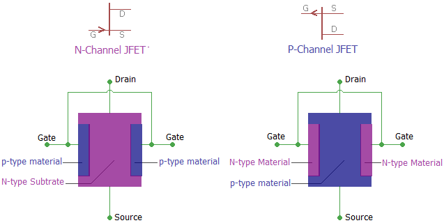
- In the case of p channel JFET, the channel is formed by a P-type semiconductor bar and too heavily doped n-type regions are formed on the two sides of the p-type bar forming the channel. In FET, current flows through the channel from the left-hand end (called source) to the right-hand end (called a drain).
The main function of jfet is to modulate the current between the channel and the source with the variation of the applied gate voltage, as it is a voltage-controlled device.
- (vgs = 0) If no voltage applied to the door, it allows maximum current through the source and drain.
- (vgs <0) With the reverse bias of the gate-source junction, there should be a nearly zero current across the gate connection.
- (vgs >0) and finally, if the gate-source junction is forward biased with a small voltage, the channel will open a little further to allow larger currents through it, causing damage to the transistor.
However, jfet connections are not built to handle the substantial flow itself, and hence it is not recommended to continue-bias the gate intersection under any circumstances.
Consider n-channel fet:-
Let’s say we apply a positive voltage at the gate source w.r.t.
The channel voltage must be positive to pull the electrons from the source into the drain.

So now p + has positive voltage and ntype type will have positive voltage.
let vds = 0 initially, and vgs positive = 1 is applied.
now p-n material will represent diode with anode voltage as voltage vgs and cathode as vds. so now in this case the va-vk is greater than 0.7v.
So the diode will be forward biased and also the width of the depletion region will decrease, the height of the potential barrier will decrease.
P Channel Jfet Working

now maximum channel width just in case. so when vds is applied the maximum current will flow through the channel and this current will continue to increase with vds.
Now jfet will have some resistance, say r. so that power will be given as p = id ^ 2 * r and this power is described in the form of heat. so the transistor will burn .
Also if at input we apply input junction positive voltage will get forward bias. because the input resistance of the jfet will be small. so the loading effect will occur.
Source or output of the previous amplifier can be loaded because of inputs to the reduced jfet due to loading effect.
P Fet Characteristics
You should also determine whether you are talking about channel p or n channel jfet.
If the p channel then apply a positive voltage between the source and the gate is ok to work from the channel behavior.
If n channel, then there will be no pinch off at low voltage and the behavior will have higher drain to source id current with respect to gate zero to source voltage
The main advantage of jfet is the reverse bias gate junction because the current drawn by this device from the source is reduced to near zero and hence offers a very high impedance i / p, which is highly desirable.
Pjfit
This advantage will be lost if you use jfet in forward bias.
Depends whether jfet is n-channel or p-channel.
If the n-channel then increases the vgs in the positive direction it will increase the charge -ve in the channel and therefore increase the current flow.

If the p-channel then increases the vgs in the negative direction increases the + ve charge in the channel and therefore increases the current flow.
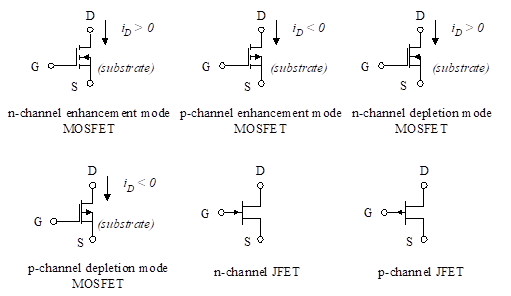
Following are the N-channel JFET(junction field effect transistor) and P-channel JFET .
| N-channel JFET | P-channel JFET |
|---|---|
| The current conduction takes place due to electrons. | The current conduction takes place due to holes. |
| Mobility of electrons large. | Mobility of electrons poor. |
| Its transconductance is large. | Its transconductance is small. |
| N-channel JFET is superior in circuit applications. | It is less superior in circuit applications. |
| It is less noisy. | It is comparatively more noisy. |
| Symbol of N-channel JFET | Symbol of P-channel JFET |
Jfet P Channel And N Channel
Related Articles:


